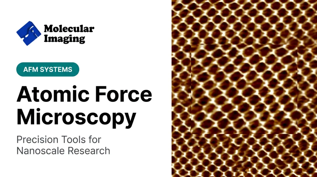
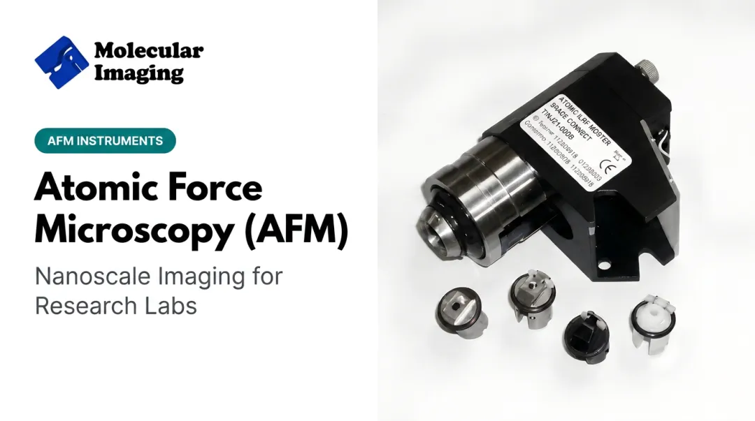
The technique isn't slowing down either. The global AFM market is projected to grow from $541.8 million in 2025 to $762.2 million by 2030, a 7.1% CAGR, driven largely by expanding use in biological research and battery/materials R&D, according to MarketsandMarkets' 2025 industry report.
Yet many researchers who use AFM daily still misunderstand what's happening inside the instrument. That gap leads to wrong mode selections and misread data. This guide breaks down exactly how AFM works, stage by stage, from tip-sample interaction to final image.
Key Takeaways
- AFM maps surfaces by scanning a sharp tip on a flexible cantilever and reading force-induced deflection
- A laser-and-photodiode system tracks cantilever motion; feedback electronics turn that signal into topography
- Imaging runs in four stages: initiation, core scanning, feedback regulation, and image output
- Contact, tapping, and non-contact modes match different sample types and resolution needs
- Labs use AFM in materials science, nanotechnology, and life sciences for imaging and force measurement
What Is AFM?
AFM is a scanning probe microscopy (SPM) technique that builds images by physically "feeling" a surface with a sharp probe, rather than bouncing light or electrons off it.
Binnig, Quate, and Gerber introduced the concept in a landmark 1986 Physical Review Letters paper. They designed it as an extension of scanning tunneling microscopy (STM) that could image insulating surfaces, not just conductive ones, at atomic scale.
That distinction still matters. AFM is not optical or electron microscopy: it isn't bound by the diffraction limit of light, and it doesn't bombard the sample with a beam. It's also not STM.
STM measures a tunneling current between tip and sample, which only works on conductive materials. AFM measures mechanical force, so it works on both conducting and insulating samples, per NIST's technical documentation.
Why AFM Still Matters Next to Electron Microscopes
Electron microscopes deliver high resolution, but they typically demand vacuum conditions and conductive coatings. AFM doesn't.
- Operates in ambient air or liquid, with no vacuum chamber required
- Images conducting and non-conducting samples without special coating
- Captures mechanical, electrical, and topographic data in one pass
Bruker notes that polymer work by AFM needs neither vacuum nor a conductive covering, which is one reason the method is common on soft materials.

AFM comes in several operating modes, static and dynamic, covered later in this guide.
How Does AFM Work?
AFM builds an image through a defined sequence: mount the sample, bring the tip close, let forces bend the cantilever, and convert that bending into a picture. Each stage below shapes measurement accuracy.
Initiation
The process starts with mechanical setup. A cantilever-tip assembly and sample are mounted on a piezoelectric stage, and a laser is aligned onto the back of the cantilever so its reflection lands precisely on the photodetector.
Tip approach itself is largely automated. Piezoelectric actuators and feedback electronics inch the tip toward the surface slowly, avoiding a sudden "snap-in" that can crash the probe into the sample.
This is also where a lot of imaging problems originate. A contaminated, dull, or mismatched probe at this stage causes poor resolution or outright tip damage, no matter how good the electronics are downstream. Matching the cantilever to the sample matters:
- Stiff silicon or silicon nitride probes for contact mode on rigid films
- Frequency-matched tapping cantilevers for air-environment scanning
- Liquid-specific cantilevers for biological or electrochemical samples in fluid
Researchers can source calibrated cantilevers, STM tips, and grating calibration samples through Molecular Imaging's web store to rule out probe mismatch before it wastes a scan session.
Core Operation
As the tip nears the surface, several forces come into play: van der Waals attraction, electrostatic forces, capillary forces at longer range, and mechanical contact forces up close. These bend the cantilever according to Hooke's Law: F = kq, where k is the cantilever's spring constant and q is the deflection, as described in a 2017 Scientific Reports study.
Here's the mechanical loop in action:
- The tip raster-scans the sample across an x-y grid
- A laser reflects off the cantilever's back onto a segmented photodiode
- Nanometer-scale deflection shifts change where the laser lands on the detector
- This voltage signal is logged, pixel by pixel, as the scan progresses
Scanning speed, cantilever stiffness, and the chosen interaction mode all directly affect resolution, throughput, and the risk of damaging the sample. A stiff cantilever scanning fast might blur soft biological features; a soft cantilever moving too quickly might not track topography accurately at all.
Regulation and Control
None of the above works without a feedback loop holding things steady. In contact mode, the loop continuously adjusts the z-height of the piezoelectric scanner to keep cantilever bending constant. In dynamic (tapping) mode, it maintains a constant oscillation amplitude instead, according to NIST's AFM overview.
Piezo scanners themselves need periodic attention. Published research documents creep during slow scans, hysteresis during large-range scans, and cross-axis coupling that can distort images if left uncorrected, according to a 2020 review in Measurement. NIST separately confirms that hysteresis and drift reduce piezo positioning accuracy.
Without precise force control, excessive tip-sample interaction can:
- Damage the probe tip, requiring replacement
- Deform or destroy delicate samples
- Introduce imaging artifacts that compromise research-grade data
There's no universal calibration schedule that fits every lab or sample type, but regular sensitivity and drift checks are non-negotiable for quantitative work.
Output and Result
The feedback signal, logged pixel by pixel, becomes a pseudocolor 3D topographic map. Depending on the mode and setup, researchers can also pull force-distance curves, stiffness (Young's modulus) measurements, or conductivity maps from the same scan.
This output feeds directly into downstream decisions: surface roughness analysis for quality control, mechanical property mapping for material selection, or electrical property data for semiconductor work.

High-resolution AFM output has produced results that other techniques could not. A widely cited example: researchers used high-speed AFM to directly visualize individual myosin V molecules walking along actin tracks, capturing the lever-arm swing mechanism in real time, published in a 2010 Nature study.
Kanazawa University described it as the first high-resolution video footage of individual protein-molecule movement.
The same methods show up across samples labs actually run. Molecular Imaging's application examples include protein S-layer assemblies, lipid bilayers on mica, and living endothelial cells imaged in liquid with MAC Mode on the 5500 AFM.
Polymer morphology comparisons on block copolymer and PMMA surfaces are documented there as well.
AFM Imaging Modes
Mode selection shapes everything, from resolution to whether your sample survives the scan intact.
| Mode | How It Works | Best For |
|---|---|---|
| Contact | Tip stays in continuous physical contact; a low-stiffness cantilever tracks the surface | Fast scanning on rigid samples; higher risk to soft materials |
| Tapping | Cantilever oscillates near resonance for intermittent contact | Soft, biological, or liquid/ambient samples; reduces lateral forces |
| Non-contact | Tip oscillates above the surface, detecting attractive forces without touching | Delicate samples; atomic-resolution vacuum imaging |
Contact mode offers the most direct signal but drags lateral forces across the surface, which can smear or displace loosely attached material.
Tapping mode was developed for samples too fragile for contact mode that still need high-resolution imaging, per Bruker's TappingMode documentation. It is now the default choice for most biological and ambient-air work.
Non-contact mode avoids tip wear and sample disturbance almost entirely, tracking van der Waals attraction instead of repulsive contact forces. It is the mode of choice for atomic-resolution vacuum studies. Atomic-resolution results in vacuum, as demonstrated by NIST's qPlus sensor work, should not be assumed for every non-contact setup at ambient conditions.
Where AFM Is Used
AFM's ability to work in air or liquid—without vacuum, coating, or staining—covers samples electron microscopy often can't.
Materials science and nanotechnology
- Thin-film and nanostructure characterization for roughness and mechanical properties
- Battery electrode research, including in-situ monitoring of solid-electrolyte interphase (SEI) formation
- Polymer morphology, crystallinity, and height/roughness mapping without vacuum or conductive coating
Life sciences and bio-imaging
- Cells, proteins, and biomolecules imaged in liquid, near their native state
- Dynamic protein–DNA interactions examined in situ, without labeling or population averaging
- Hydrated biological samples studied directly in buffer—no fixation required
Electrochemistry and molecular electronics
Shared facilities and labs studying charge transport at nanoscale junctions need modular AFM/STM platforms with real environmental control.
Typical needs include:
- In-situ electrochemistry and battery research under controlled atmosphere
- Reactive-gas and polymer studies on temperature-controlled stages
- Simultaneous imaging and electrical measurement at molecular junctions
Platforms such as Molecular Imaging’s AFM/STM line support this work with temperature stages from -30°C to 250°C and environmental isolation chambers.

Conclusion
AFM's precision comes down to one thing: combining mechanical force sensing with tight electronic feedback across four connected stages (initiation, core operation, regulation, and output). Get any one stage wrong—a dull tip, a poorly calibrated scanner, or an ill-suited mode—and the data suffers.
Understanding this sequence helps researchers make better calls on probe selection, mode choice, and system configuration before a scan ever starts. For labs evaluating new or replacement systems, Molecular Imaging's modular AFM/STM instrumentation and ZoomAFM repair support offer a path to dependable, research-grade results without starting from scratch.
Frequently Asked Questions
What does AFM stand for?
AFM stands for Atomic Force Microscopy, a high-resolution scanning probe technique also known as scanning force microscopy (SFM). It images surfaces by measuring mechanical force rather than light or electron beams.
What is AFM in engineering?
In engineering, AFM characterizes surface topography, mechanical properties, and electrical behavior at the nanoscale. It's commonly applied in semiconductor and materials engineering for defect analysis and thin-film testing.
What is the difference between AFM and STM?
AFM measures mechanical force through cantilever deflection and works on both conductive and non-conductive samples. STM measures tunneling current instead, which requires a conductive sample surface.
What resolution can AFM achieve?
AFM can reach subnanometer, even atomic-scale, resolution under the right conditions. That's well beyond the roughly 200 nm limit of conventional optical microscopy.
Can AFM be used to image living cells or biological samples?
Yes. AFM images biological samples, including living cells and proteins, particularly in tapping or non-contact mode within liquid environments. No staining or fixation is required.
What are the three main AFM operating modes?
The three primary modes are contact, tapping (intermittent contact), and non-contact. Choice depends on sample fragility, desired resolution, and acceptable risk of tip or sample damage.