Bruker, one of the largest AFM manufacturers, calls TappingMode the "most popular AFM imaging mode", noting it lets researchers image fragile samples that would be damaged under Contact Mode, while scanning faster than true Non-Contact Mode.
The problem: many operators treat it as a preset button. They select "Tapping" from a dropdown menu and never learn what the cantilever is actually doing at the tip. That gap shows up later as blurry images, chewed-up probes, or phase data nobody on the team can interpret correctly.
This guide breaks down the mechanics behind the mode, not just the textbook summary.
TL;DR
- Cantilever oscillates near resonance, tapping once per cycle instead of dragging across the sample
- Amplitude changes drive the topography feedback loop; phase lag reveals material contrast
- Tip cycles between attractive and repulsive force zones in each oscillation
- Lower lateral force than Contact Mode suits soft, biological, and polymer samples
- Go-to mode across materials science, semiconductor metrology, and BioAFM workflows
What Is Tapping Mode?
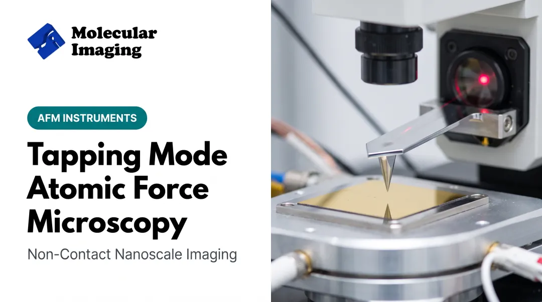
Tapping Mode is a dynamic, intermittent-contact AFM technique. A cantilever oscillates above the sample surface, and the tip touches down only briefly at the bottom of each cycle. The system tracks how that oscillation amplitude changes and uses those changes to reconstruct the surface topography.
It exists because of a gap between two older approaches:
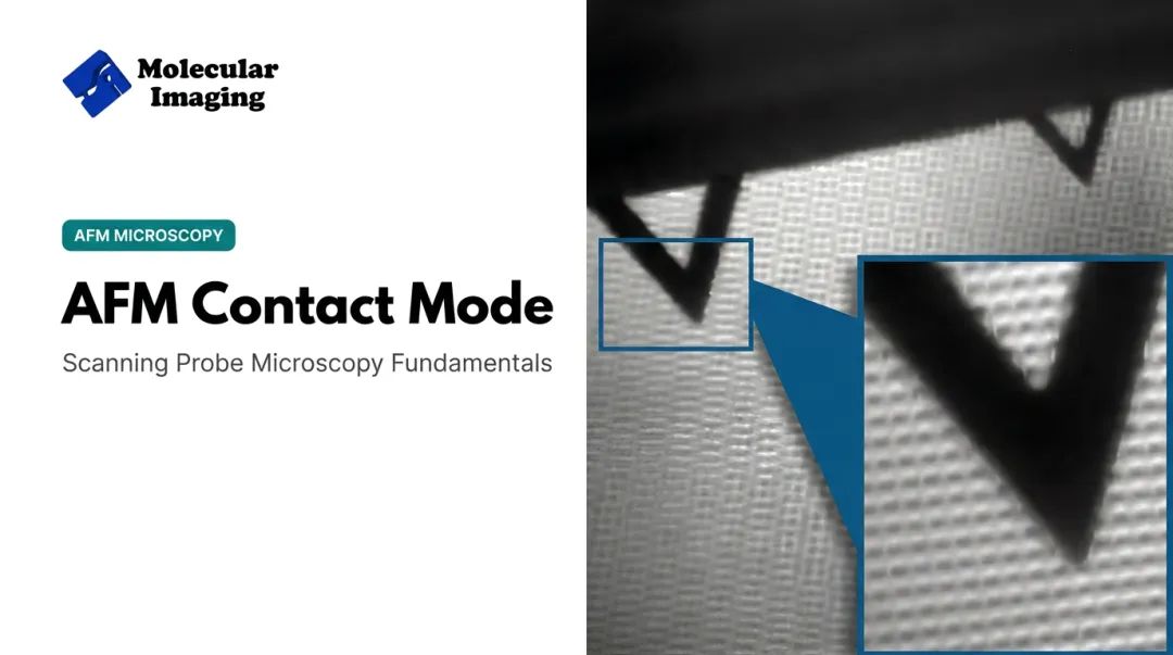
- Contact Mode keeps the tip in constant contact, generating high lateral shear forces that scratch soft samples and wear tips quickly.
- True Non-Contact Mode avoids contact altogether but relies on weaker attractive-force signals, which makes feedback less stable.
Tapping Mode sits between these two: intermittent contact with feedback driven by amplitude, not constant deflection. Oxford Instruments' Asylum Research division describes it as a way to measure interaction-induced amplitude changes — the core distinction from Contact Mode.
Why It Still Beats Newer Alternatives for Most Labs
Techniques like PeakForce Tapping and PinPoint nanomechanical mode extract more quantitative data per tap. But Tapping Mode remains the default because it's:
- Simpler to set up and tune.
- More robust across a wider range of sample types.
- Faster to scan than most non-contact approaches.
- Compatible with air and liquid environments without extra hardware.
The Resonance Frequency Foundation
Every Tapping Mode setup starts with one equation:
f₀ = (1/2π)√(k/m)
Here, f₀ is the cantilever's resonance frequency, k is its spring constant, and m is the effective mass of the lever (not the total physical mass). That relationship drives cantilever choice:
- Softer, low-k levers oscillate at lower frequencies and apply gentler force — better for delicate or biological specimens.
- Stiffer, higher-frequency levers push harder and scan faster — better for robust materials.
Operators also talk about three practical variants:
- Light tapping — a soft setpoint that minimizes force
- Hard tapping — a more aggressive setpoint for speed or stability
- Phase imaging — material-contrast data layered on topography without a separate scan

How Does Tapping Mode Work?
Tapping Mode runs through four connected stages: initiation, core operation, regulation and control, and output. Understanding each one explains why images sometimes come out sharp and other times come out grainy or unstable.
Initiation
The process starts when the operator selects Tapping Mode and the instrument sweeps a range of drive frequencies to find the cantilever's natural resonance. Bruker's software documentation describes this as a "Cantilever Tune" step, where the system plots amplitude and phase against drive frequency to locate the peak.
Frequency identification is largely automated on modern systems, but the operator still sets the drive amplitude and the amplitude setpoint, either manually or through an auto-tune routine.
This is where a common bottleneck starts. If the cantilever's spring constant doesn't match the sample, tracking becomes unstable from the first line scan. A stiff cantilever on a soft polymer film, for example, can apply excessive force before the feedback loop even engages.
Matching probe to sample here matters more than most new users realize.
Core Operation
Once tuned, the cantilever oscillates at large amplitude near resonance. As the tip approaches the surface, changing tip-sample forces shift the effective spring constant, which in turn shifts the resonance condition itself.
Here's what happens physically during one oscillation cycle:
- For most of the cycle, the tip stays in the attractive force regime, pulled gently toward the surface by van der Waals forces
- At the lower turning point, it briefly crosses into the repulsive regime, making momentary physical contact
- As it rises, the tip withdraws back through the attractive regime before the next cycle begins
This attractive-to-repulsive transition sits on the Lennard-Jones potential curve, and it's the defining feature separating Tapping Mode from both Contact and true Non-Contact operation. A 1999 study in Physical Review B documented exactly this distinction, separating "attractive" and "repulsive" tapping regimes based on which force dominates the amplitude response.
The resulting amplitude change is what the system reads as its raw signal. Small distance variations produce measurable shifts in oscillation amplitude, and that sensitivity is what ultimately shapes achievable image resolution.
Regulation and Control
A feedback loop compares the measured amplitude against the operator's setpoint continuously. When the amplitude drifts from that setpoint, meaning the tip is encountering more or less resistance than expected, the system adjusts the Z-scanner height to restore it. Park Systems describes this Z-scanner motion as the direct source of the topography trace.
A second signal rides alongside amplitude: phase. This is the lag between the drive signal sent to the cantilever and the oscillation it actually detects. Phase lag shifts with local mechanical differences such as stiffness, adhesion, and viscoelasticity, giving a qualitative map of material contrast layered over the height data.
This regulation stage does three jobs at once:
- Prevents tip crashes by catching sudden topography changes before they cause damage
- Limits excessive force that would otherwise accelerate tip wear
- Keeps imaging stable across uneven or textured surfaces
Output and Result
The scan produces two images from one pass: a height (topography) map built from Z-scanner movement, and a phase map showing relative material contrast. Neither requires extra hardware; both come from the same oscillation data, processed differently.
These outputs feed directly into downstream work, including roughness quantification, particle sizing, thin-film thickness analysis, or correlation with electrical and mechanical data in multimodal studies.
Getting clean output at this stage depends heavily on the electronics underneath. Molecular Imaging's AFM platforms use low-noise electronics and closed-loop scanners to keep amplitude and phase readings stable during longer scans, which matters when a single drift event can ruin an otherwise good dataset.

Advantages and Limitations of Tapping Mode
Tapping Mode's biggest strength is what it avoids: constant lateral dragging. Because contact happens only at the bottom of each oscillation, shear forces stay low, which is why it's the default choice for soft, biological, and polymer samples.
Where it performs well:
- Works in both air and liquid environments without added hardware
- Delivers phase contrast as a built-in secondary channel
- Handles fragile samples that Contact Mode would tear or compress
Where it runs into limits:
- Intermittent contact still wears the probe faster than true Non-Contact imaging
- Soft or sticky samples can cause tip adhesion, dragging material onto the probe
- Phase data stays qualitative—calibrated modulus or adhesion values need advanced modes such as PeakForce QNM
When you need quantitative mechanical mapping beyond phase contrast, Molecular Imaging supports Pulsed Force Mode and multi-frequency (Eigen Mode) imaging, plus diamond-coated indentation cantilevers built for repeated hardness work without rapid tip wear.
Mode selection comes down to three questions: how hard is the sample, what environment it needs, and whether the study needs qualitative or quantitative data. Answer those, and Tapping Mode’s place in the workflow is usually clear.
Where Is Tapping Mode Used?
Tapping Mode is typically the first imaging step after sample preparation. Researchers use it to establish a reliable topography baseline before switching to specialized or higher-force modes when the study demands it.
It performs best in dry, ambient-air conditions on hard-to-moderately-soft samples, and in liquid or temperature-controlled setups for biological and electrochemical work.
Across research segments:
- Materials science and thin films: A 2020 Scientific Reports study used ambient Tapping Mode AFM to map rubrene nanostructures in organic semiconductor films, linking morphology to transport behavior
- Electrochemical surface analysis: In-situ Tapping Mode variants have captured ordered nanostructures at electrode interfaces in deep-eutectic solvents
- BioAFM imaging: A 2021 DNA structural research review documented plasmid DNA in water and dsRNA helical pitch of 3.1 ± 0.3 nm in fluid
For liquid and biological work, Molecular Imaging's 5500 ILM PicoPlus BioAFM uses MAC Mode, a magnetically driven tapping variant that reduces fluid-induced background noise compared with standard acoustic drive.
Paired with temperature-controlled stages (−30°C to 250°C) and environmental isolation chambers for humidity and gas control, the same oscillation principle extends from dry semiconductor wafers to live cells in buffer.

Conclusion
Tapping Mode's logic boils down to one loop. An oscillating cantilever taps the surface once per cycle. Amplitude changes drive the Z-feedback that builds topography, and phase lag adds material contrast on top.
Knowing that logic changes how you operate the instrument. It means:
- Picking a cantilever spring constant that matches your sample
- Setting a setpoint that doesn't overdrive the tip
- Reading phase data as qualitative contrast, not a calibrated number
It also means working with a partner who understands the mechanics, not just the software. Whether you need the right tapping cantilever, a BioAFM set up for liquid imaging, or help with unstable amplitude tracking through ZoomAFM repair and support, Molecular Imaging works from the same physics this guide covered.
Frequently Asked Questions
What is the resonance frequency formula for Tapping Mode?
The cantilever resonance frequency formula is f₀ = (1/2π)√(k/m), where k is the spring constant and m is the effective mass of the lever. This sets the drive frequency the instrument targets during Tapping Mode setup.
What are the three types of tapping?
Light tapping uses a gentle setpoint for delicate samples; hard tapping uses a more aggressive setpoint for robust samples or faster scanning. Phase imaging is a related channel that maps material contrast alongside topography, not a separate tapping type.
What is the difference between Tapping Mode and Contact Mode AFM?
Contact Mode keeps the tip in continuous contact with the surface, generating lateral drag that can damage soft samples. Tapping Mode makes intermittent contact once per oscillation cycle, reducing that shear force.
Can Tapping Mode be used to image soft or biological samples?
Yes. Its reduced lateral force makes it well suited to soft and biological samples, especially with low-spring-constant cantilevers and light setpoints. Specialized BioAFM systems extend this further for imaging in liquid environments.
Why does Tapping Mode wear out AFM tips faster than Non-Contact Mode?
In Tapping Mode, the tip makes brief physical contact at the bottom of every oscillation, gradually blunting the probe over repeated cycles. True Non-Contact Mode stays in the attractive force regime and avoids that contact pathway entirely.
What is phase imaging in Tapping Mode AFM?
Phase imaging measures the lag between the signal driving the cantilever and the oscillation it actually detects. That lag shifts with local stiffness, adhesion, and composition, giving a qualitative map of material contrast.