Introduction
A microfabricated beam thinner than a human hair does the heavy lifting in every atomic force microscope. The AFM cantilever, often under a millimeter long, is the single sensing component responsible for sub-nanometer resolution imaging.
Many researchers struggle with cantilever selection. Pick the wrong material, geometry, or spring constant, and you get blurry images, worn-out tips, or samples damaged beyond use. Wrong probes waste runs, burn budget, and leave you with data you cannot publish.
This guide covers cantilever anatomy, the main types and materials, and the parameters that affect your images. It also explains the forces at play, how AFM compares with SEM and TEM, and how to choose, maintain, and source probes for your lab.
Key Takeaways
- The cantilever and tip form the AFM's core sensor, deflecting according to Hooke's law in response to surface forces
- Material, geometry, spring constant, and resonance frequency determine which cantilever fits your imaging mode
- Contact mode needs soft, low-stiffness cantilevers; tapping mode needs stiffer, higher-frequency ones
- Cantilevers are consumables — proper handling and periodic replacement preserve image quality
- Reliable probe sourcing and technical support directly affect long-term instrument performance
What Is an AFM Cantilever?
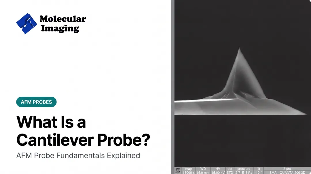
An AFM cantilever is a microfabricated, spring-like beam, typically 100 to 450 micrometers long, with a sharp tip at its free end. It's mounted on a support chip that slots into the microscope's scanning head, letting researchers swap probes between experiments.
As the tip moves across (or near) a sample surface, tip-sample forces bend or oscillate the cantilever. That motion follows Hooke's law: deflection is proportional to force, scaled by the cantilever's stiffness.
A detection system converts this deflection into an electrical signal, and that signal becomes the topographic image, as described in a 2023 review of AFM cantilever mechanics.
Anatomy of the Cantilever and Tip
Every cantilever has three structural elements:
- The beam — silicon or silicon nitride, generally 0.5 to 7 µm thick, providing the spring mechanism
- The tip — a sharp probe at the free end with an apex radius typically between 2 and 15 nm, depending on the product line
- The reflective coating — usually aluminum or gold, applied to the detector-facing side to boost laser reflectivity for signal detection
Coating choice matters more than it seems. Manufacturer data shows a 30 nm aluminum layer can increase reflectance by roughly 2.5 times. Gold coatings serve a similar function but are often favored for aqueous or biological work because they hold up better in certain chemical environments.
Coatings bring tradeoffs too. Poorly balanced coating stress can bend the cantilever. Bruker's probe specifications note stress-induced bending under 2 to 4 degrees on comparable gold-coated designs, which is why manufacturers keep coating thickness tightly controlled.
Tip geometry varies by application:
- Pyramidal and conical tips for general topographic imaging
- High-aspect-ratio, whisker-like tips (including carbon nanotube tips) for imaging deep trenches and steep sidewalls
- Spherical or colloidal probes for mechanical property studies or chemically functionalized force spectroscopy

How Cantilever Deflection Is Measured
Most commercial AFMs use optical beam deflection: a laser reflects off the cantilever's back onto a position-sensitive photodetector. Small deflections shift the reflected beam's position, and the detector translates that shift into a measurable signal.
Other detection methods exist for specialized setups:
- Piezoresistive sensing, useful when optical access is limited
- Capacitive detection for certain vacuum systems
- Interferometric methods for high-precision metrology applications
Types of AFM Cantilevers: Geometry, Material & Mode Compatibility
Cantilever shape changes how the probe responds to lateral and vertical forces.
Rectangular ("diving board") cantilevers offer predictable, easily calculated spring constants, which is why they're the go-to for tapping mode. Triangular ("V-shaped") cantilevers resist lateral torsion better, making them a common choice for contact mode where sideways drag forces are constant.
Material Tradeoffs: Silicon vs. Silicon Nitride
- Silicon tips are typically sharper (apex radii under 8 nm; guaranteed under 12 nm on standard lines) but wear faster under repeated contact
- Silicon nitride tips are slightly less sharp (typically under 10 nm), yet thinner, more flexible, and more wear-resistant due to low-stress fabrication
Molecular Imaging's catalog reflects this split directly. The ContSi-10 is a silicon contact-mode probe built for high-resolution topographical work, while the S3N4-10 uses silicon nitride for extra durability in the same imaging mode.
Matching Cantilevers to Imaging Mode
| Mode | Spring Constant | Resonance Frequency | Example Use |
|---|---|---|---|
| Contact mode | Under 0.1 N/m | Low (tens of kHz) | Soft or delicate samples |
| Tapping/non-contact | Above 1 N/m | Hundreds of kHz | Harder surfaces, faster scans |
Molecular Imaging's tapping-mode lineup shows this range in practice:
- NCH-30-10: higher frequencies for minimal-damage imaging in air
- NCL-30-10: balanced resolution and stability for general-purpose scanning
- FM-10: low-frequency, soft operation for delicate biological samples
Specialized Coatings and Constructions
Beyond standard imaging, specialty cantilevers support additional measurement types:
- Conductive coatings (platinum, gold, doped silicon) for STM, EFM, and electrochemical AFM, including Molecular Imaging's EFM-10 and Conductive Contact Cantilever
- Magnetic coatings for MFM: the MFM-10 maps magnetic domain structures at the nanoscale
- Diamond coatings for indentation and hardness testing on hard materials: the Diamond-10
- Functionalized tips (biomolecules, carbon nanotubes) for bio-AFM and molecular electronics research
When comparing probe options across suppliers, expect commercial cantilevers to fall roughly in this range: length 90–450 µm, width 13–50 µm, thickness 0.5–7 µm.
Key Cantilever Parameters That Affect AFM Performance
Spring Constant and Manufacturing Tolerance
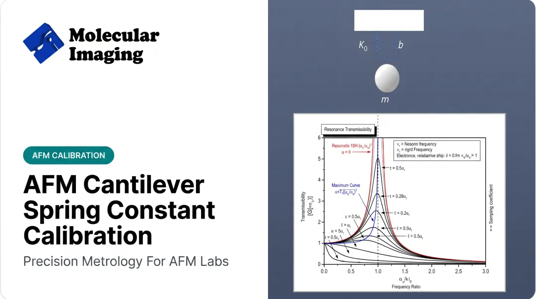
The spring constant (k), measured in N/m, comes from a beam's geometry and material properties. For rectangular cantilevers, NIST expresses it as k = Ebt³/(4L³), where thickness and length are both cubed terms.
That cubing matters. A NIST reference standard publication shows that a ±20% thickness variation, holding everything else constant, shifts the actual spring constant by roughly -49% to +73%.
A cantilever labeled 0.5 N/m could easily behave like 0.25 N/m or 0.85 N/m in practice. Calibration isn't optional: it's the only way to know what you're actually working with.
Resonance Frequency and Q-Factor
Shorter, stiffer cantilevers vibrate at higher resonance frequencies. In tapping and non-contact modes, those higher frequencies generally support faster, more stable imaging.
The Q-factor measures energy loss per oscillation cycle. It changes dramatically depending on environment:
- Roughly 50–500 in air
- Roughly 2–10 in liquid, according to a peer-reviewed dynamic force microscopy study
That's about a two-order-of-magnitude drop from viscous damping alone. Lower Q reduces sensitivity in liquid imaging, which is why needle-tip and small-cantilever designs exist to recover some of that lost performance.
Tip Sharpness and Wear
Apex radius (commonly 1 to 15 nm) governs lateral resolution directly. A sharper tip resolves finer features. But every scan blunts the tip a little, and a worn probe distorts everything it touches.
Comparative imaging of a polypropylene film using sharp versus blunt probes showed the blunt probe enlarging feature dimensions, flattening profiles, and shrinking apparent hole sizes.
A known 2-nanometer-high object imaged with a damaged tip can appear correctly tall but 10–20 nm wide, because the tip shape gets convolved into every measurement. Multi-apex tips (chipped or contaminated) go further, producing duplicate "ghost" features across the image.

Practical takeaway: match spring constant, resonance frequency, and tip material to sample hardness before you start scanning. Swapping a stiff tapping-mode probe onto a soft polymer sample, or a soft contact-mode probe onto a hard ceramic, is a fast route to either sample damage or a blunted, useless tip.
Forces That Govern Cantilever-Sample Interactions
Cantilever deflection comes from a mix of forces that shift with imaging mode and environment:
- Van der Waals forces: sum of Keesom, Debye, and London dispersion contributions between essentially all atoms
- Electrostatic/double-layer forces: attractive and repulsive components on charged surfaces in liquid
- Capillary/meniscus forces: from adsorbed water films in ambient air
- Chemical bonding: short-lived adhesive interactions during contact
- Magnetic forces: relevant specifically for magnetic force microscopy (MFM)
What Stops the Tip From Crashing Into the Sample?
Once the tip gets within roughly 0.3 nm, electron orbitals on the tip and sample begin to overlap. That overlap produces Pauli repulsion, a short-range force strong enough to stop the tip from penetrating the surface, as shown in Princeton-led atomic-scale imaging research.
Contact-mode imaging operates in this repulsive regime. The tip reaches it only after passing through the attractive "snap-in" zone, where long-range forces briefly overcome the cantilever's stiffness.
Why Tapping Mode Exists
In ambient air, a thin water layer coats most surfaces. When a cantilever tip approaches, capillary forces pull it into a meniscus that can dominate — and mask — the weaker van der Waals attraction. For soft or biological samples, that pulling force is often enough to smear or damage delicate structures.
Those same capillary forces are why dynamic tapping mode exists. By oscillating the tip and only briefly touching the surface each cycle, tapping mode cuts the time spent inside the destructive meniscus zone and protects soft or biological samples.

AFM vs SEM vs TEM: How Cantilever-Based Imaging Compares
AFM works differently from electron microscopy. It uses a physical cantilever and tip to "feel" surface topography in three dimensions, with no lenses and no vacuum required.
SEM and TEM instead rely on electron beams, which demand a high-vacuum environment (confirmed for TEM by Microscopy Australia's training materials) and, for TEM specifically, extremely thin samples to produce a 2D projection image.
For research labs, AFM's practical advantages are significant:
- Operates in ambient air or liquid, ideal for life-science and bio-AFM samples
- No conductive sample coating required for standard topographic imaging
- Captures mechanical or electrical properties simultaneously alongside topography
There's a genuine tradeoff, though. AFM scan areas are modest (commercial systems typically scan in the tens of micrometers, not millimeters), and imaging speed runs slower—often several minutes per high-quality frame compared to SEM's near-instant acquisition.
For large-area or real-time imaging needs, SEM remains the faster tool. For nanoscale 3D surface detail in native, unmodified conditions, AFM is hard to beat.

Choosing, Handling & Sourcing the Right AFM Cantilever
Selection and Care Best Practices
Before ordering a probe, run through this checklist:
- Match spring constant and resonance frequency to your imaging mode: soft and low-k for contact, stiff and high-frequency for tapping
- Verify coating compatibility with your sample environment: air versus liquid changes which coating makes sense
- Choose tip material based on sample properties: hardness, conductivity, or biological sensitivity all point toward different materials
Cantilevers are fragile consumables. A few handling basics help protect tip life:
- Use ESD-safe handling procedures to avoid static damage to the fine tip structure
- Store probes in a clean, dry environment away from dust and vibration
- Use solvent immersion or UV-ozone treatment to remove organic contamination and extend tip life
Sourcing Reliable Cantilevers, Probes & Support
Cantilever quality and availability affect every image your lab produces. Molecular Imaging's web store carries cantilevers for contact mode, tapping mode, liquid-environment imaging, MFM, EFM/KFM, diamond-coated indentation, and conductive AFM.
These probes are compatible with all major brand AFM systems. Calibration samples and sample accessories are available to complete a working setup.
Labs running older instruments face a separate challenge: keeping the system itself running. ZoomAFM offers repair, diagnostics, calibration, and preventive maintenance for legacy Agilent and Molecular Imaging systems.
Technical documentation, video tutorials, and application support give researchers a practical path through cantilever selection and imaging troubleshooting.
Frequently Asked Questions
What is a cantilever in atomic force microscopy?
A cantilever is the spring-like microfabricated beam with a sharp tip that deflects in response to surface forces. That deflection is the core signal an AFM uses to build its topographic image.
What repulsive forces keep an AFM tip from penetrating the sample?
Short-range Pauli repulsion, caused by overlapping electron clouds at roughly 0.3 nm separation, balances attractive forces once the tip gets extremely close. This prevents physical penetration during contact-mode imaging.
What is the difference between AFM, TEM, and SEM?
AFM uses a physical probe to map 3D surface topography in ambient air or liquid. SEM and TEM use electron beams under vacuum, producing 2D surface or internal structural images respectively.
What material are AFM cantilevers usually made of?
Silicon and silicon nitride are the two dominant materials, chosen for sharpness versus durability tradeoffs. Specialty options include diamond-coated and quartz cantilevers.
How often should I replace an AFM cantilever?
Replace cantilevers when tip wear, contamination, or breakage visibly degrades image quality. How often that happens depends on sample hardness, scanning mode, and how hard the probe contacts the surface.
How do I choose the right spring constant for my cantilever?
Use soft, low spring-constant cantilevers (under 0.1 N/m) for contact mode on delicate samples. Choose stiffer, higher-k cantilevers for tapping or non-contact mode on harder surfaces.