That's the gap Magnetic Force Microscopy fills. Many magnetic imaging tools demand conductive samples, invasive sample prep, or simply can't resolve features below a few hundred nanometers. MFM sidesteps all three problems by sensing magnetic force gradients directly, without ever touching the sample.
This guide covers how MFM actually works, the hardware behind it, its imaging modes, where it's used across industry and research, and what to look for in an MFM-capable AFM system.
Key Takeaways
- MFM is an AFM-based technique that uses a magnetized tip to detect magnetic force gradients without touching the sample
- Dual-pass lift-mode scanning separates magnetic signal from surface topography on most systems
- Bright contrast indicates repulsive force gradients; dark contrast indicates attractive ones
- Works on conductive and non-conductive samples in air, vacuum, liquid, or under variable temperature and field conditions
What Is Magnetic Force Microscopy (MFM)?
MFM is a scanning probe technique built on Atomic Force Microscopy (AFM). Instead of a standard silicon tip, MFM uses a magnetized cantilever tip that senses dipole-dipole interactions between the tip and the sample's magnetic stray field. The result is a map of magnetic domain structure at resolutions conventional optical tools can't touch.
The technique isn't new. Y. Martin and H.K. Wickramasinghe first demonstrated it in 1987, publishing a paper in Applied Physics Letters reporting 1000 angstrom (100 nm) resolution using a magnetic force microscope. That work built on two earlier developments: Binnig, Quate, and Gerber's Atomic Force Microscope (1986) and Binnig and Rohrer's Scanning Tunneling Microscope (1982).
Unlike techniques that require electrical conductivity or destructive sample prep, MFM images both conductive and non-conductive magnetic materials with minimal alteration. You don't need to sputter-coat your sample or slice it into a cross-section. You just scan it.
What Is an AFM Image?
A standard AFM image is a topographic map. The tip raster-scans across the surface, and height variations at each point get converted into pixel brightness — taller features appear brighter (or darker, depending on the color scale), building up a 3D-like surface map.
MFM output works differently. A single scan typically generates two images:
- A topography image from the first pass, showing surface height
- A magnetic phase or frequency image from the second, lifted pass, showing magnetic contrast
Both are necessary. Without the topography reference, it's easy to mistake a surface bump for a magnetic domain boundary — a common misread for anyone new to the technique.

How Does MFM Work? The Working Principle Explained
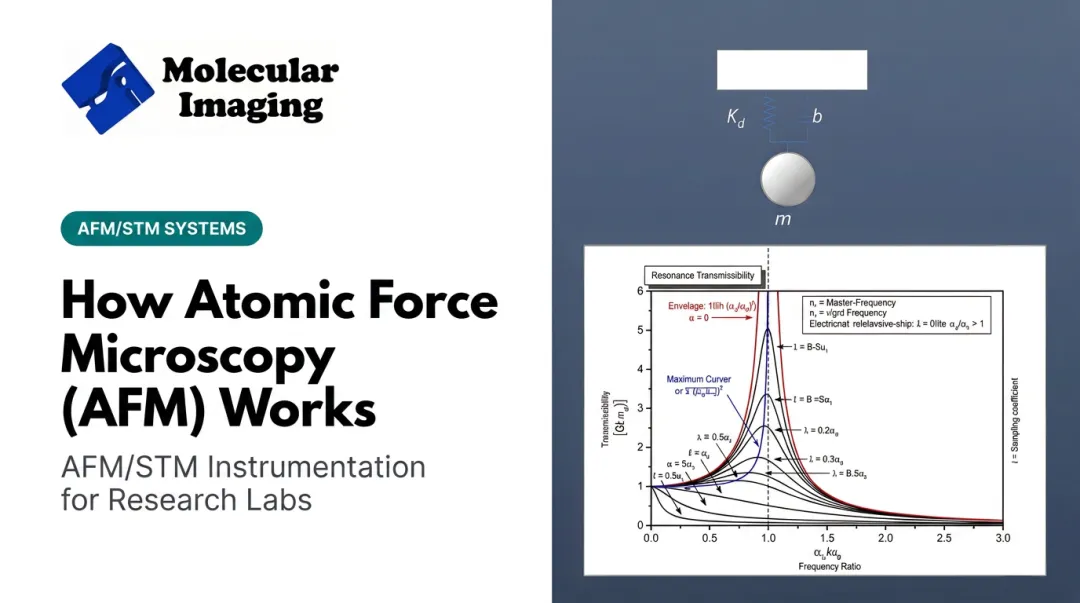
The physics is straightforward, even if the engineering isn't. A magnetized tip mounted on a flexible cantilever sits above a magnetic sample. The sample's stray magnetic field exerts a force (and a force gradient) on the tip through dipole-dipole interaction. That gradient bends the cantilever or shifts its resonance, and the instrument reads that shift as signal.
Most modern MFM systems run in dynamic (AC) mode. The cantilever oscillates near its resonance frequency, typically somewhere in the tens to hundreds of kHz range. Here's what happens to that oscillation as the tip passes over different magnetic regions:
- A repulsive force gradient shifts resonance higher → appears as bright contrast
- An attractive force gradient shifts resonance lower → appears as dark contrast
Lift height is the variable that makes or breaks image quality. Set it too high, and you lose resolution because the tip sits too far from the sample's magnetic field to sense fine detail. Set it too low, and short-range topographic forces bleed into the magnetic signal, corrupting the data.
There's no single "correct" lift height ; it depends on the sample. A 2024 study published in the Review of Scientific Instruments describes dual-pass second-pass heights commonly ranging from tens of nanometers up to about 100 nm. The researchers settled on 60 nm after accounting for thermal drift. Sample roughness, tip sharpness, and instrument stability all factor into the right setting for your experiment.
Lift-Mode Scanning: Single-Pass vs. Dual-Pass Techniques
Two approaches dominate MFM scanning:
Single-pass MFM scans the tip at a constant height, capturing topography and magnetic signal simultaneously in one pass. It's faster, causes less tip wear, and simplifies interpretation , but you sacrifice some resolution since you can't optimize height separately for each signal type.
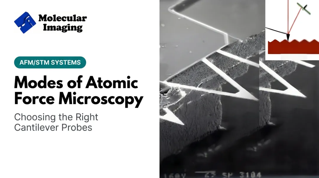
Dual-pass (lift mode) MFM is the more widely used method. The tip:
- Scans each line first in tapping mode to map topography
- Retraces the same line at a user-defined lifted height to capture pure magnetic signal, free of short-range atomic forces
Dual-pass scanning takes longer, but it's the standard choice when accuracy matters more than speed, as it does in most research applications.
Interpreting MFM Contrast: Attractive vs. Repulsive Forces
Once you know bright means repulsive and dark means attractive, contrast becomes a map of real magnetic structure. Researchers use it to locate domain walls, read recorded bit patterns on storage media, and track how magnetization rearranges when an external field is applied.

MFM System Components and Modes of Operation
Key Hardware Components of an MFM System
Three components define an MFM setup:
- Piezoelectric scanner — moves the sample (or tip) in x/y/z with nanometer-scale precision per volt applied
- Magnetized cantilever-tip assembly — thin high-coercivity magnetic coating (historically Co or Ni alloys) that gives the tip a stable magnetic moment
- Cantilever material — silicon or silicon nitride; spring constant sets sensitivity and force resolution
Molecular Imaging's web store lists the MFM-10 cantilever for domain-structure mapping, part of a broader probe catalog that also covers contact mode, tapping mode, and EFM/KFM cantilevers.
Modern MFM tips are largely batch-fabricated using micromachining and photolithography. That's a meaningful upgrade over older etched-metal tips — batch fabrication gives you more consistent, controllable magnetic dipole geometry from tip to tip, which matters when you're trying to compare scans across samples or over time.
Static (DC) vs. Dynamic (AC) Mode
MFM can run in two fundamentally different detection modes:
| Mode | Detection method | Typical sensitivity |
|---|---|---|
| Static (DC) | Direct cantilever deflection | Tens of piconewtons |
| Dynamic (AC) | Resonance frequency or phase shift | Piconewton to sub-piconewton range |
Dynamic mode dominates modern instruments. Measuring a frequency or phase shift is more sensitive and less noise-prone than raw deflection, especially for the weak, long-range forces magnetic samples produce.
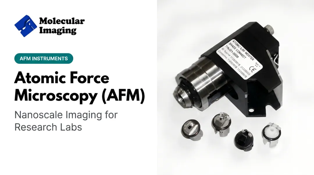
That is why virtually every commercial MFM system sold today defaults to dynamic mode, including the modular nose-cone configurations on Molecular Imaging's 5500 PicoPlus platform.
Applications of MFM in Research and Industry
Data storage was MFM's original proving ground and remains one of its most practical uses. Labs use it for quality control on hard disk platters and magnetic tape, visualizing recording tracks and magnetization reversal patterns.
Specialized tip coatings push resolution well past commercial defaults. A 2012 study in the Journal of Applied Physics achieved 7.3 to 10.2 nm resolution using Fe-B coated tips, distinguishing individual 14.9 nm-long recorded bits. Standard commercial probes typically deliver around 25 nm under ambient conditions, which is plenty for most quality-control workflows.
Materials science relies on MFM to map magnetic domains and domain walls in thin films, nanoparticles, and nanowires. Documented examples include:
- Imaging of 180-degree Bloch walls in iron single crystals
- Tracking domain-wall nucleation and motion in cylindrical permalloy nanowires under small applied fields
This kind of imaging lets researchers correlate magnetic behavior directly with crystal anisotropy or structural defects.
Spintronics research is an emerging frontier. MFM has been paired with non-local spin-transport measurements on operating graphene spin valves, linking electrode magnetization behavior to transport signals in real time.
That approach differs from combining MFM with conductive-AFM. Molecular Imaging's PicoPlus 5500 platform supports both MFM and Current Sensing AFM through modular nose cones, so labs can pursue combined measurements on a single system.
Advanced materials development benefits from MFM as one piece of a broader characterization toolkit. Polymer composites embedded with magnetite have been mapped with combined AFM/MFM to assess distribution and topography together. Magnetic thin films, including topological insulator materials, have been studied through systematic MFM domain analysis.

Battery electrode research at Molecular Imaging typically runs through complementary techniques rather than MFM specifically:
- In-situ electrochemical AFM
- Kelvin Probe Force Microscopy
- Environmental isolation chambers built for humidity and gas control
Life sciences is an expanding application area: characterizing magnetic nanoparticles used in biomedical imaging and drug delivery research.
Peer-reviewed work has measured magnetosomes and iron-oxide nanoparticles at lift heights as low as 20 nm, with particle sizes resolved down to roughly 11 nm. Drug delivery applications remain a forward-looking research direction rather than a fully established clinical use, but the characterization groundwork is well underway.
Advantages, Limitations, and Choosing the Right MFM System
Advantages of MFM
- Works on samples that are not electrically conductive
- Measures nondestructively: no coating, slicing, or chemical prep
- Operates in ambient, vacuum, liquid, and variable temperature or magnetic field conditions
- Requires no special surface treatment before scanning
Limitations to Consider
MFM has real trade-offs worth planning for:
- Nonlinear tip-sample magnetization interactions can complicate interpretation, especially on samples with strong or complex stray fields
- Lateral scan range is limited (commercial systems such as the Bruker Dimension Icon and Oxford MFP-3D Origin typically top out around 90–120 µm), so MFM is a poor fit for large-area surveys
- Detected forces are weak, so systems need solid acoustic and vibrational isolation for reliable results
Those constraints shape what matters when you pick an MFM-capable AFM: modular modes, environmental control, and service support for existing instruments.
Why Choose Molecular Imaging for MFM-Capable AFM Systems
Molecular Imaging's modular AFM/STM platforms, especially the 5500 PicoPlus series, support MFM as a swappable nose-cone mode alongside KPFM and EFM. One instrument handles magnetic imaging without a dedicated MFM system.
The revival team includes former Molecular Imaging professionals with hands-on experience in application support, engineering, and R&D, guided by academic advisor Dr. Stuart Lindsay.
For labs that need controlled MFM conditions or ongoing instrument support:
- Temperature-controlled stages from -30°C to 250°C with anti-drift design
- Environmental isolation chambers for humidity, temperature, and gas control during sensitive scans
- ZoomAFM diagnostics, recalibration, and repair for older AFM/STM systems still in service

Frequently Asked Questions
What is the working principle of MFM?
A magnetized tip is lifted above the sample to sense long-range magnetic force gradients, typically using dynamic mode. Resonance frequency and phase shifts encode attractive and repulsive magnetic contrast as bright and dark regions.
What is an AFM image?
An AFM image is a topographic map created by raster-scanning a tip across a surface and converting height variations into pixels. This differs from the magnetic phase image MFM produces during its lifted second pass.
What is the difference between AFM and MFM?
Standard AFM measures surface topography using short-range atomic forces between tip and sample. MFM is a specialized AFM mode that uses a magnetized tip to detect long-range magnetic forces instead.
What resolution can MFM achieve?
Typical MFM resolution sits around 20 to 30 nm with standard commercial probes. Specialized tip coatings have pushed resolution down to roughly 7 to 10 nm in research settings, depending on tip sharpness and lift height.
Can MFM be used on non-magnetic or non-conductive samples?
MFM requires the sample to produce some magnetic stray field to detect — it won't work on completely non-magnetic materials. However, unlike many imaging techniques, it does not require the sample to be electrically conductive.
What is lift height in MFM and why does it matter?
Lift height is the distance the tip is raised above the sample during the second pass of dual-pass scanning. That distance balances magnetic sensitivity against topographic crosstalk; the ideal height depends on the sample.