Many researchers blame "noisy tips" or "bad samples" when the real culprit is a poorly aligned laser, an untuned gain loop, or a scan rate that's simply too fast for the topography. Poor setup and parameter choices remain the leading cause of distorted, artifact-riddled nanoscale images.
This guide walks through setup fundamentals, the four parameters that matter most, a repeatable optimization workflow, and how to diagnose the artifacts that show up when something's off.
Key Takeaways
- Setpoint, gain, scan rate, and resolution control image quality and artifacts more than any other settings
- Optimize in order: scan rate first, gains second, setpoint last
- Comparing trace/retrace curves diagnoses most probe, scanner, and noise artifacts
- Match probe, stage, and environment to the sample so mode changes stay fast and repeatable
Understanding AFM Setup Basics
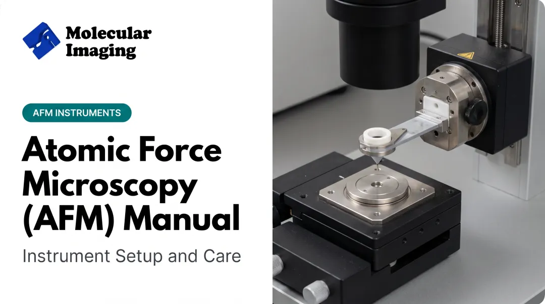
Before you touch a single scanning parameter, the physical setup has to be right. A standard sequence: mount the sample, install the correct cantilever/probe, align the laser onto the cantilever, then center the reflected beam on the photodetector.
Choose your imaging mode before configuring anything else:
- Contact mode: feedback holds cantilever deflection constant
- Tapping/intermittent mode: feedback holds oscillation amplitude constant after intermittent tip-sample contact
- Non-contact mode: also controls oscillation amplitude, but at greater tip-sample distance to limit sample damage
Mode determines which signal your feedback loop is trying to hold steady. That decision shapes every setup step that follows, including which cantilever you install and how you tune resonance.
Environmental Setup Matters More Than You'd Think
Floor vibration commonly shows up as horizontal banding in images. Footsteps or a nearby elevator can transmit through the floor, so labs typically use:
- Vibration-isolation tables
- Ground-floor or below-grade instrument placement
- Acoustic hoods to block conversation and HVAC noise
For biological or polymer samples, temperature stability matters too. Small thermal drifts can shift the tip tens or hundreds of nanometers mid-scan, distorting scale and shape.
The feedback loop and z-piezo controller maintain tip-sample distance throughout the scan. Verify this loop is stable before you start collecting data, not after you've already got a distorted image on screen.
When mode choice, isolation, and feedback all have to stay aligned, a modular AFM reduces setup friction. Molecular Imaging's 5500 PicoPlus platform uses a top-down scanner with selectable ranges from 9 × 9 µm for atomic-resolution work up to 90 × 90 µm for larger-area imaging.
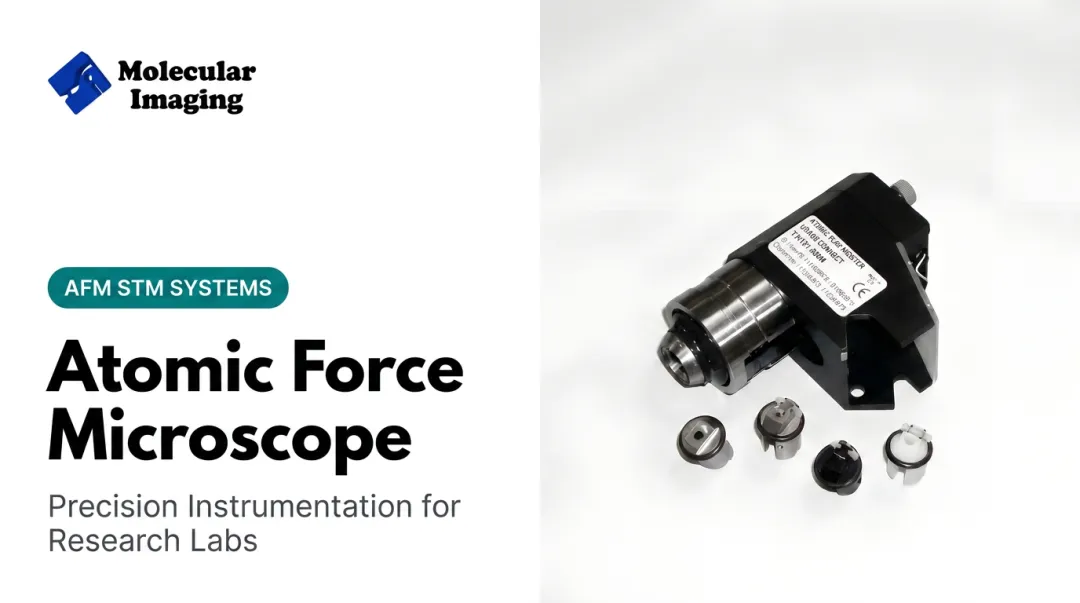
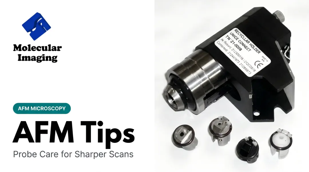
Quick-change nose cones support AFM, STM, tapping, KPFM, EFM, MFM, and force measurement on the same base unit. One platform can move from DNA imaging in liquid to hard-material characterization without swapping instruments.

Initial Calibration Checks
Run these before every serious scan:
- Confirm laser alignment — verify the reflected spot is centered on the photodetector
- Check cantilever resonance (tapping mode) — tune to the correct frequency before engaging
- Scan a calibration sample — verify lateral and vertical accuracy against a known standard, such as a 500 nm periodic grating or gold-on-mica reference
Skipping this step is how researchers discover, mid-experiment, that their "nanoscale feature" was actually a scanner artifact.
Core Scanning Parameters Explained
Five parameters control most of what you see in an AFM image. Setpoint governs tip-sample interaction force. Increase it and you reduce noise but lose fine detail. Decrease it and you gain detail but accelerate tip wear. It's a direct tradeoff, not a "set it and forget it" number. Drive amplitude (tapping mode) sets how hard the cantilever oscillates before contact. Rougher samples typically need larger free amplitude. The amplitude setpoint (the target amplitude after intermittent contact) is usually expressed as a percentage of free amplitude; lowering it increases the force of interaction. Gain (proportional and integral) controls how fast the feedback loop reacts to topography changes.
- Higher gain = faster tracking, but risks oscillation and high-frequency noise
- Lower gain = smoother signal, but risks the tip failing to follow real features
- Ideal gain = trace and retrace overlap closely without ringing or overshoot
Scan rate trades speed for fidelity. As a rough starting point, large scans with tall features often need 0.5–1.0 Hz, while flat samples with small scan areas can tolerate much higher rates. Resolution (pixel count) trades image detail against total scan time. More pixels per line means more time per frame, with no guarantee of better physical resolution. Pixel count is digital sampling, not proof of real resolution. For context on what's achievable: a peer-reviewed 2023 review on high-speed AFM for biological macromolecules reports 2–3 nm lateral and roughly 0.1 nm vertical spatial resolution under well-controlled conditions. That's a benchmark, not a universal guarantee. Your actual numbers depend heavily on tip geometry, calibration, and environment.

Step-by-Step Parameter Optimization Workflow
Skip the temptation to fiddle with everything at once. Optimize in this order.
Step 1: Scan Rate First
Compare trace and retrace height curves at a moderate scan rate. Reduce speed gradually until the two curves closely overlap. If they diverge, your tip isn't tracking the surface fast enough at that speed.
Step 2: Gains Second
With scan rate set, increase integral gain until you see the onset of piezo oscillation. Then back off two or three clicks. Repeat for proportional gain. You're looking for the fastest possible response that doesn't introduce ringing or noise.
Step 3: Setpoint Last
Finally, decrease the setpoint (or amplitude setpoint in tapping mode) gradually to improve tracking and feature detail. Watch for signs of excessive tip wear: this is the parameter most directly tied to probe lifespan.
How do you know you're done?
- Trace and retrace curves overlap tightly
- Minimal visible noise in the height channel
- Feedback loop stays stable across the full scan
One caveat: don't assume "optimized once" means "optimized forever." If you move to a new region with dramatically different topography (for example, from a flat terrace to a tall nanoparticle cluster), revisit scan rate and gain before trusting the new data.

Common Imaging Artifacts and Troubleshooting
Most artifacts fall into three categories, and trace/retrace comparison is your best diagnostic tool for telling them apart.
Probe-related artifacts:
- Double-tip imaging or repeated "ghost" features usually mean a contaminated or damaged tip
- Uniform triangular shapes across unrelated features are a classic sign of tip-shape convolution, not real topography
- Fix: swap the probe and re-image a calibration sample before trusting new data
Scanner artifacts:
- Hysteresis and curved backgrounds stem from nonlinear piezo response to voltage, especially at larger scan sizes
- Calibration samples, like a 500 nm grating or gold-on-mica standard, reveal these distortions quickly
- Fix: recalibrate the scanner and, where needed, apply trace/retrace correlation correction
Noise and process artifacts:
- Ambient vibration produces horizontal banding
- Electronic interference shows up as high-frequency noise unrelated to topography
- Excessive scan speed causes poor tracking, visible as trace/retrace disagreement
- Fix: use vibration isolation, lower gain and check grounding, and slow the scan until trace and retrace agree
| Symptom | Likely Cause | Fix |
|---|---|---|
| Repeated ghost features | Damaged/contaminated tip | Replace probe, retest on calibration sample |
| Curved image background | Scanner hysteresis | Recalibrate scanner |
| Horizontal bands | Floor vibration | Isolation table, relocate |
| High-frequency noise | Electronics or excess gain | Reduce gain, check grounding |
| Poor tracking / trace-retrace mismatch | Excessive scan speed | Slow scan rate until traces agree |

Choosing the Right AFM System and Support for Reliable Results
Parameter tuning only gets you so far if the underlying system, probes, or documentation aren't up to the task. Long-term imaging accuracy depends on all three working together.
Molecular Imaging's modular AFM/STM platforms, including the 5500 PicoPlus and Benchtop 5400, are built around interchangeable scanners, nose cones, and probe types. Labs running mixed workloads (biological samples one week, hard materials the next) aren't stuck reconfiguring from scratch.
The company also maintains a technical documentation library covering installation, calibration, hardware connections, and troubleshooting. That resource helps when a setup issue isn't obvious from the manual alone.
For labs with existing instruments showing wear or drift, ZoomAFM provides repair, calibration, and preventive maintenance for Agilent AFM and STM systems, including diagnostic support and remote troubleshooting via video conferencing.
Environmental control accessories also matter for repeatability:
- Temperature-controlled stages spanning −30°C to 250°C for thermal studies
- Environmental isolation chambers for humidity, low-oxygen, and gas control in battery, polymer, and reactive-gas work
- Liquid cells and sample modules for in-liquid biological and electrochemical imaging
These accessories separate a one-off good image from a dataset you can defend in a publication.
Frequently Asked Questions
How much does an AFM cost?
AFM systems vary widely in price depending on modularity, automation features, and application-specific accessories like liquid cells or environmental chambers. Contact Molecular Imaging for a configuration-based quote.
How accurate is AFM?
Under well-controlled conditions, properly calibrated AFM can achieve lateral resolution of a few nanometers and vertical resolution approaching 0.1 nm. Actual accuracy depends on tip geometry, scanner calibration, and environmental stability. It is not a fixed spec.
What is the first parameter I should adjust when optimizing an AFM scan?
Start with scan rate/tip velocity, comparing trace and retrace curves until they overlap. Adjust gain next, then fine-tune setpoint last.
Why does my AFM image look noisy even after adjusting the setpoint?
Noise that persists after setpoint changes usually points to gain settings, ambient vibration, or electronic interference. Check trace/retrace agreement and your isolation setup before blaming the probe.
Can AFM scanning parameters differ between contact and tapping mode?
Yes. Tapping mode introduces drive amplitude and phase parameters that don't exist in contact mode, so tuning approaches differ between the two.
How often should I recalibrate my AFM before scanning?
There's no universal fixed schedule, but check calibration before switching to a new sample type or after any probe change, using a reference calibration sample to confirm accuracy.