That's where atomic force microscopy earns its place in the nanomechanics toolkit. AFM nanoindentation combines nanoscale imaging with load-displacement measurements, letting researchers probe hardness, elastic modulus, adhesion, and creep behavior on samples that would fall apart under a conventional indenter.
This guide walks through how AFM nanoindentation works, what properties it measures, where it's used, and what to look for in an AFM/SPM system if you're building out this capability.
Key Takeaways
- AFM nanoindentation pulls hardness, modulus, adhesion, creep, and fracture data from calibrated load-displacement curves
- Excels on soft, small, or fragile samples (hydrogels, cells, MOF nanocrystals, 2D nanosheets) where bulk nanoindentation fails
- Reliable numbers need tip calibration, the right contact model (Oliver-Pharr, Hertz, Sneddon), and sink-in/pile-up control
- Modular AFM/SPM platforms switch between imaging and force measurement—no second dedicated instrument required
What Is AFM Nanoindentation?
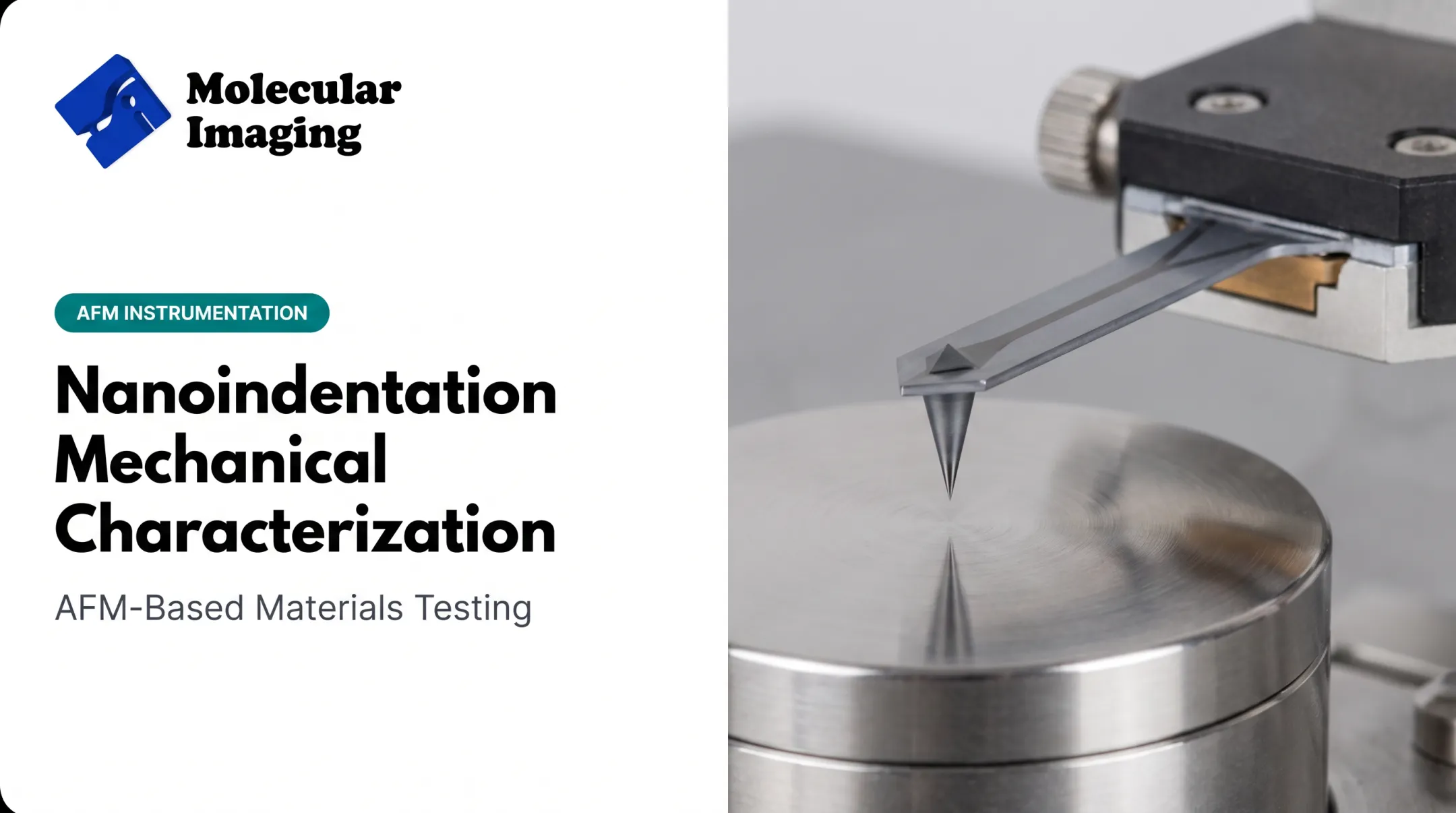
AFM nanoindentation uses a calibrated cantilever tip to press into a surface while recording force and displacement in real time. The output is a load-displacement (P-h) curve: a direct record of how the material deforms under load at the nanoscale.
In general terms, nanoindentation means pressing a hard tip of known geometry into a material and analyzing the load-displacement response for properties such as hardness and stiffness. Of AFM's three operating modes (contact, tapping, non-contact), contact mode underpins indentation work: the tip stays in physical contact with the sample as controlled force is applied, which is what produces a usable P-h curve.
How AFM Differs From Conventional Nanoindentation
The two techniques aren't interchangeable. They occupy different niches:
- Force range: Conventional nanoindentation typically runs about 0.3–5 mN; AFM peak-force work can reach ~10 pN (2022 review in Musculoskeletal Research)
- Sensitivity trade-off: AFM offers orders-of-magnitude greater force and displacement sensitivity, while conventional systems retain the edge in dynamic range and standardized force characterization
- Contact volume: AFM indents involve far smaller effective contact volumes, ideal for individual nanocrystals or thin coatings
Practically, that means AFM isn't a universal replacement for conventional nanoindentation — it's a complement that opens up low-load, small-volume, and local mapping work that bulk instruments can't touch.
The measurement itself relies on piezo-driven positioning. A tip of known geometry (cube-corner, Berkovich, or diamond-coated pyramid) presses into the surface at a controlled rate. With tip shape known, researchers extract hardness and modulus from the peak load and contact area.
How AFM Nanoindentation Is Performed
The basic workflow follows a predictable sequence:
- Approach — the tip moves toward the sample surface under piezo control
- Load — controlled force is applied until reaching a user-defined maximum
- Hold or retract — the tip either dwells at peak load (for creep studies) or withdraws immediately
Researchers then fit the resulting P-h curve using an established model. The Oliver-Pharr method remains the standard: it treats the loading response as elastic-plastic and the initial unloading segment as elastic, extracting hardness, stiffness, and Young's modulus from that fit.

Where the Assumptions Break Down
Oliver-Pharr and related contact models rest on assumptions that often fail in practice. They generally assume:
- Isotropic material response
- Negligible sink-in or pile-up effects
- A linear-elastic half-space with frictionless contact
Crystalline materials often violate isotropy, producing orientation-dependent sink-in and pile-up that skew contact-area estimates. AFM has one advantage here: it can image the residual indent directly rather than relying purely on the model's geometric assumption, according to research published in Applied Surface Science.
Best-fit sample types for this technique:
- Soft solids and polymers
- Biological samples (cells, proteins)
- Hydrogels
- 2D nanosheets
- Nanocomposites and porous nanocrystals
The MOF Case Study
A clear demonstration comes from ZIF-8 metal-organic framework crystals. Researchers used a calibrated diamond cube-corner AFM tip to measure nanocrystals below 500 nm and crystals around 2 μm, samples far too small for conventional testing, which previously required crystals around 100 μm, according to research archived at Oxford University.
The resulting modulus values, roughly 3-4 GPa, agreed with earlier bulk measurements. AFM solved a specimen-scale problem conventional testing could not address.

Key Nanomechanical Properties Measured
AFM nanoindentation doesn't return a single number. Depending on the protocol, it can extract five distinct categories of mechanical behavior.
Hardness and Elastic Modulus
These two travel together. Hardness reflects resistance to plastic deformation; elastic modulus captures stiffness recovered during unloading. Both come from fitting the unloading segment of the P-h curve, with accuracy hinging on correct tip geometry and contact-area assumptions.
Adhesion Energy and Interfacial Strength
For micro- and nanocrystals too small for bulk adhesion testing, AFM quantifies the work needed to separate tip and sample from a force-distance cycle. This value is highly sensitive to protocol: pull-off force and contact-radius methods can disagree, especially when contact time or loading rate shifts.
Creep Deformation
Holding the tip at roughly constant force reveals time-dependent penetration. An AFM study on MgO single crystals held a pyramidal tip at 2 μN and varied dwell time from 0.001 to 10 seconds. Penetration increased noticeably once dwell times exceeded 0.1 seconds, per research in Materials Science Letters. Thermal stability during these hold periods is essential for clean data.
Storage and Loss Moduli
Viscoelastic materials (polymers, hydrogels, many biomaterials) need frequency-dependent analysis rather than a purely elastic fit. Storage modulus captures elastic energy storage; loss modulus captures viscous dissipation. Neither shows up in a simple Hertz fit.
Fracture Toughness
By imaging residual indent shapes and any resulting cracks in situ, AFM supports crack-length-based toughness estimates. This is model-dependent work, not a single standardized test, but it's often the only practical route for brittle nanoscale samples.

Applications Across Research Fields
AFM nanoindentation shows up wherever bulk testing can't reach.
Materials science benefits most directly. Thin films, coatings, and MOF crystals like ZIF-8 all require local, small-volume measurement. A general rule of thumb: keep indentation depth below 10% of film thickness to avoid substrate interference.
Life sciences and bio-AFM extend the technique into liquid environments. Researchers map the mechanics of live cells, proteins, and hydrogels in physiological buffers. Reported cell stiffness values span roughly 1-100 kPa depending on cell type, a range wide enough that consistent probe geometry matters more than the raw number.
Battery, polymer, and electrochemical research often demand environmental control alongside mechanical measurement. Molecular Imaging's accessory lineup supports these conditions:
- Environmental isolation chambers control humidity, temperature, and gas atmosphere for battery and reactive-gas studies
- Temperature-controlled sample stages operate from -30°C to 250°C for polymer phase-transition work
- Liquid cells enable stable in-liquid indentation for electrochemical and bio samples
These accessories don't replace the core measurement. They let researchers hold conditions steady while indenting samples that are otherwise sensitive to ambient drift.

Challenges and Limitations of AFM Nanoindentation
No technique is free of trade-offs, and AFM nanoindentation has several worth planning around.
Tip wear distorts everything downstream. In one wear study on rough titanium and diamond surfaces, tip radii changed measurably after just 5.1 mm of sliding contact. Tested cases reached 36 ± 4 nm and 31 ± 4 nm, according to a tip-wear study on titanium and diamond (PMC). A worn tip skews contact-area calculations and every derived property that depends on them.
Surface constraints matter too:
- Rough surfaces make contact-radius assumptions unreliable
- Flat, smooth regions are strongly preferred for consistent results
- Topographic imaging before indentation helps verify actual contact area
Reproducibility suffers from several compounding factors:
- Viscoelastic samples show rate-dependent apparent modulus — one cell study found higher loading rates produced larger measured stiffness
- Adhesive interactions during unloading depend on contact time and force rate, not just material properties
- Indentation rate effects mean two labs testing the "same" sample can get different numbers if protocols differ
Tip geometry presents another trade-off. Geometry chosen for imaging resolution is not always optimal for indentation accuracy. Sharper tips resolve finer topographic detail but don't always behave predictably under load.
Choosing the Right AFM System for Nanomechanical Testing
Given how much protocol and tip condition affect results, the instrument platform matters.
Modularity is the deciding factor. Switching between imaging and indentation shouldn't require buying a second system. Molecular Imaging's Pendulum Multipurpose Scanner uses interchangeable nose cones to move between conventional AFM imaging, STM, tapping mode, and force-measurement workflows on one platform, available across the Agilent 5500, 5100, and 5420 series.
For biological or in-liquid work, the 5500 ILM PicoPlus BioAFM supports force-measurement techniques alongside imaging, with scan ranges up to 90 μm × 90 μm and 0.2 nm vertical resolution.
Probe selection also matters. For indentation specifically, diamond-coated cantilevers — such as the Diamond-10 — offer the wear resistance needed for repeated hard-material testing. Standard silicon or silicon-nitride contact-mode cantilevers cover general topographical and mechanical-property work.

A few other practical considerations for labs building this capability:
- Calibration standards (grating or 500 nm periodic samples) to verify positioning accuracy before indentation runs
- Reliable repair support, such as Molecular Imaging's ZoomAFM service, to keep aging Agilent-era systems running with platform-matched replacement parts and recalibration
- Documentation and tutorials on force-curve acquisition to help new users avoid common calibration mistakes
None of this eliminates the need for careful protocol design. But starting with a modular, well-supported system removes a lot of avoidable variability.
Frequently Asked Questions
What is nanoindentation?
Nanoindentation presses a hard, known-geometry tip into a material and analyzes the resulting load-displacement data to derive hardness and elastic modulus. It's used across materials science wherever mechanical properties need to be measured at very small scales.
What is AFM used for?
AFM images surface topography at nanometer resolution and characterizes surface features across materials science and biology. In nanoindentation mode, it also measures nanomechanical properties like hardness, modulus, and adhesion.
How does AFM nanoindentation differ from traditional instrumented nanoindentation?
AFM offers shallower depth control, smaller contact volumes, and substantially higher load sensitivity — down to the piconewton range versus the millinewton range typical of conventional instruments. That makes it better suited to soft or small samples.
What materials are best suited for AFM nanoindentation?
Soft solids, biological samples, polymers, hydrogels, 2D nanosheets, and small or fragile nanocrystals all work well. These are generally samples too small, soft, or delicate for bulk instrumented testing.
What is the Oliver-Pharr method used for in nanoindentation?
It's the standard analysis approach for extracting hardness and elastic modulus from load-displacement curves. It fits the initial unloading segment, assuming elastic-plastic loading behavior.
Can AFM nanoindentation measure biological samples?
Yes. Bio-AFM protocols routinely image and mechanically probe cells, proteins, and hydrogels in liquid environments that mimic physiological conditions, using force-distance curve analysis fitted with Hertz or Sneddon models.